
Half Cat Valves
The Half Cat valve is a custom valve designed to provide high flow rates with minimal weight and size. Several iterations of this design have been built and tested, but the most recent and likely final iteration will be discussed in detail here. Information on legacy designs (pyrotechnic, hydraulic) can be found at the bottom of the page.
The key feature which enables Half Cat valves to be so simple is that they use the pressure of the working fluid, usually fuel or oxidizer, to open. All versions of the design rest on the fundamental principle of having a body which houses a piston of two diameters. When closed, working fluid is sealed by the tip of the piston and can only apply pressure on the small diameter. Meanwhile, pneumatic gas supplied to the cavity acts on the large diameter. In this way, the pneumatic supply can be lower pressure than the working fluid.
Simplifying even further, given that our motor architecture always includes nitrous oxide, there is already a high pressure supply available as a pnuematic fluid. By adding a tee to the nitrous fill line onboard the rocket, pressure will be applied to the cavity at the same time as the propellant tanks - and since the cavity has the larger diameter, the force imbalance means that the piston stays in the closed position.
To open the valves, the nitrous must simply be vented from the pneumatic cavity, either by way of severing the line or by actuating a small pilot valve in the system. Care must be taken to put a check valve in an appropriate location such that the oxidizer tank isn't dumped when the fill system upstream is vented.
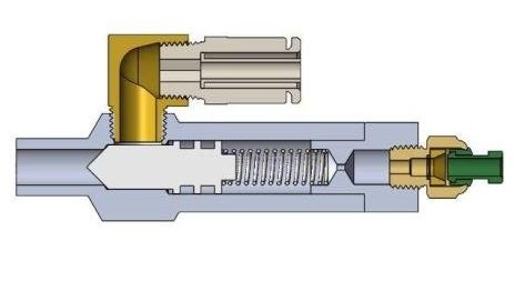
The exact size, shape, and form factor of the valve may vary but it will always take on a design like the one shown below.

The body has an inlet, along the axis, entering the small diameter, and may be tapped (for a fitting).
The body has an outlet, to the side, protruding out of the large diameter, and will be tapped.
The piston has a large diameter with two O-ring grooves that seal between pneumatic and working fluid.
The piston has a small diameter with a PTFE (Teflon) or Acetal (Delrin) seal at the tip (or may be entirely made of PTFE/Delrin.
It is important to note that when the piston multi-piece, as shown above, there must be an O-ring compressed under the head of the bolt which retains the sealing element. Otherwise, fluid would leak past it. A countersunk screw adequately preloaded may seal on its own due to sharp edge contact with the sealing element, but this has not been tried at the time of writing.
As in Full Cat, the valve may be mounted directly to the tank bulkhead(s). This eliminates multiple fittings and tubes and generally frees up space in the rocket. Bulkhead mounting is usually only possible with stacked (non-concentric) tanks. It may be convenient to make the inlet diameter the same as a tap drill (such as 1/8 or 1/4 NPT), but this is not necessary.
It is necessary to have three diameters (looking in from the cavity side) for the PTFE seal to work reliably. The sealing element nominally deforms on the sharp edge of the small diameter hole, but if there are non-trivial imperfections in either surface then it may actually seal at any point on the angled surface leading to the next largest diameter. If that next diameter up is your final large diameter, then in a worst case scenario working fluid pressure will act on the piston tip all the way out to same area as the pneumatic cavity and eliminate the force imbalance which is crucial to the valve's operation.
1Cat/4 Valve. Its piston is made entirely of PTFE or Delrin.
We recommend always including a spring in Half Cat valves for multiple reasons. Firstly, it provides a little bit of preload which forms a relatively weak seal at ambient pressure. This means that fuel (which is usually loaded well in advance of firing) won't leak out during handling; it also means that when the tanks and pneumatic cavity are coming up to pressure during nitrous fill, the piston starts out with a favorable force imbalance. If it wasn't already sealed, working fluid might immediately find its way past the small diameter, out to the large diameter, and potentially push the piston open.
Another reason for a spring is convenience. Assuming that the O-rings were lubricated prior to installation, the spring returns the piston to its sealed position as soon as pressure in the working fluid runs out (at the end of burn). As long as there's no major concern over debris contaminating the sealing element (preventing it from making good contact with the valve body), the valve requires no service and is immediately ready to be used again. Care must be taken to select an appropriate spring:
The diameter should be less than the large diameter of the piston so that it doesn't scratch the sealing surface which the O-rings slide over.
The fully compressed length should allow the piston to be fully opened and not blocking the flow path for working fluid through the body.
The force exerted at full extension (which is still partially compressed) should put some amount of pre-load on the sealing element.
The piston and pneumatic cap may have features which capture the spring and prevent it from slide off of the central axis, if it is significantly smaller diameter than the large diameter bore. The piston should always have a bind tapped hole on the large side so that it may be extracted with a threaded rod or long bolt.
The pneumatic cap can be done in several ways. For smaller sizes, where it is easy to tap male and female threads, the cap itself may be threaded (usually with straight threads and an O-ring). In larger valves it is more convenient to use a more conventional retention method; Full Cat's valves have a smooth bore with a bolt flange on the face of the body to clamp down a retaining plate. Older legacy valves had a bulkhead which was snap ring retained, although this can be quite inconvenient to use.
This is a basic diagram of the Half Cat architecture. Note how the valves receive pneumatic pressure from the same line that fills the oxidizer tank. We prefer to use a cable cutter to sever the line quickly and reliably; its placement may be anywhere on the fill system between the fill valve and check valve.

Not shown is the static vent at the top of the oxidizer tank, or the dump valve (if you choose to include one).
Note that this valve design can be scaled up or down as desired, and can be combined into other mechanisms like the automated vent valve. The ports can also be placed in different positions around the circumference depending on packaging requirements. This valve should work the same in reverse (with fluid entering to the larger diameter of the piston), although this has not yet been tested in practice.
Below you will find information on the legacy pyrotechnic valve which was used in Half Cat, and in 2Cat/3 as part of the Dual Valve Ignition System.
Legacy Pyrotechnic Valve
In the pyrotechnic variant, a small pellet of solid propellant with adequate mechanical properties is used as a structural member to hold the piston in place. As the pellet burns away, that structural member is removed and the piston is forced open. The pyro valve can be initiated with any power source capable of setting off an E-match (typically a 12V battery). Below you will find drawings for the pyrotechnic valves, along with a bill of materials to build your own.


Half Cat’s pyrotechnic valves