Servo-Actuated Ball Valve
These servo-actuated ball valves were designed to allow remote filling of nitrous oxide, and are an excellent alternative to solenoid valves for ground-support applications due to their much lower power draw and lack of duty cycle considerations.
The valve assembly can be built for around $35 USD, and requires no special tools other than access to a 3D printer.
With the addition of a Remote Control Firing System, multiple of these valves can be used to build a GSE system compatible with commercial and experimental hybrid rocket motors for a total cost of around $120 USD. Before first using them, be sure to adjust the endpoints of the servo horn to the open and close positions of the ball valve. The receiver failsafe should also be set to close a fill valve, and open a dump or purge valve - that way the system will return to a safe position if communication is lost.
Bill of Materials
3D Printer Filament (Approx. 41g)
Compact High Pressure Brass Ball Valve (McMaster 4112T23, 4112T22, or 4112T21)
M4x0.7 Metric Screws, 16mm or longer (Qty 4)
M4x0.7 Metric Hex Nuts (Qty 4)
M4 Flat Washers (Qty 8)
M4 Split Lock Washers (Qty 4)
M3x0.5 Metric Socket Head Cap Screw, 10mm Length (Qty 1)
M3 Flat Washer (Qty 1)
#8-32 Button Head or Pan Head Screw, 1/2" Length (Qty 1)
#8-32 Hex Nut (Qty 1)
Nylon Zip Tie, 0.188-inch width
Optional: #10 Flat Head Screws for Panel Mounting (Qty 2)
Build Instructions
1. Begin by printing the STL files in the orientation shown below. Both parts are designed to print without support; the Servo Valve Mount V2.STL requires bridging, so make sure your settings will handle that. The design has been tested in both PLA and PETG, and is expected to work with ABS as well. PETG or ABS is recommended for operating in high-temperature conditions.

2. Make sure that the servo horn is installed on the servo in the desired orientation. Connect the servo to whatever device you will be controlling it from, and verify that the servo horn points in the correct direction for both the valve open and valve close commands.
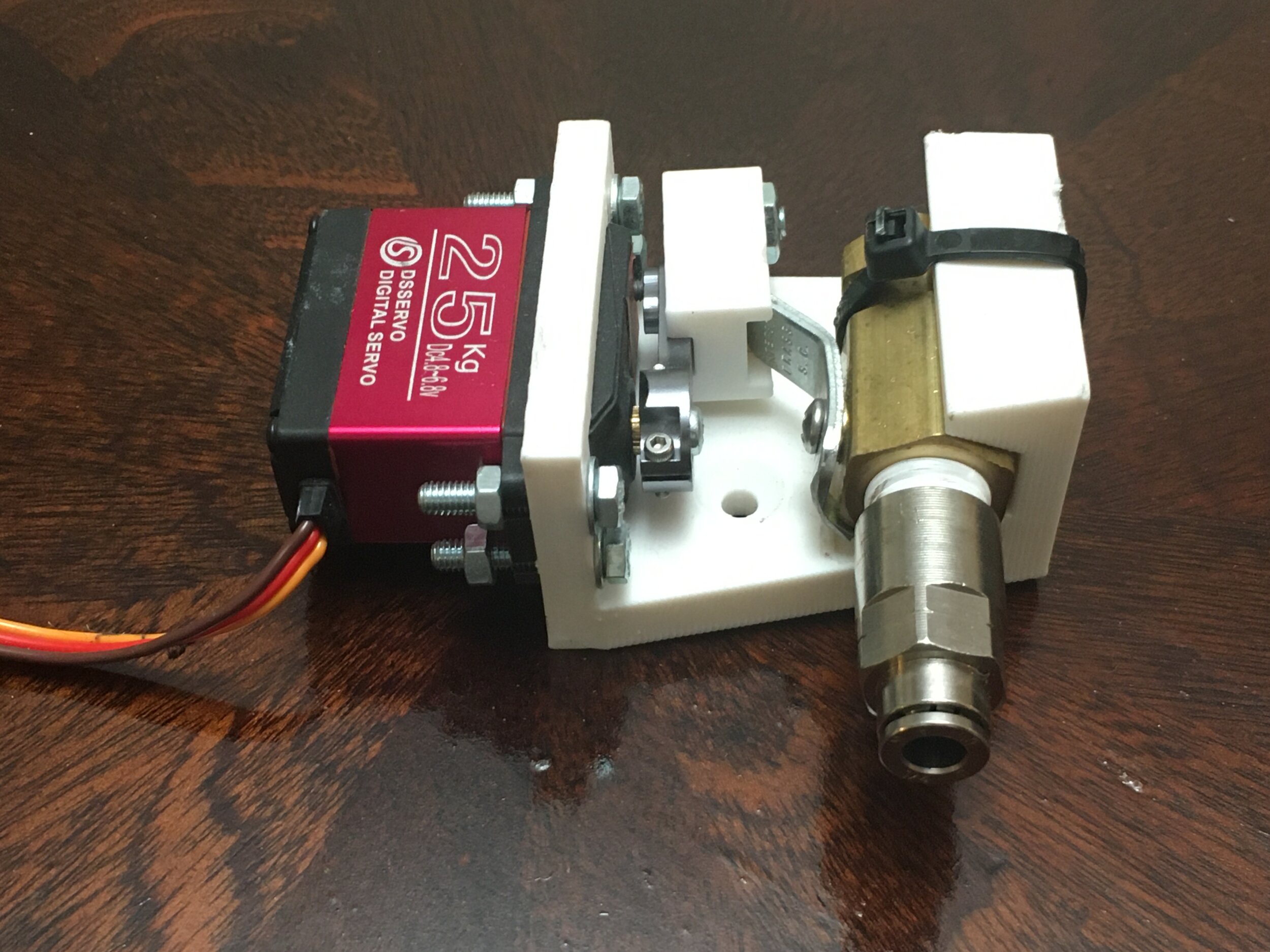
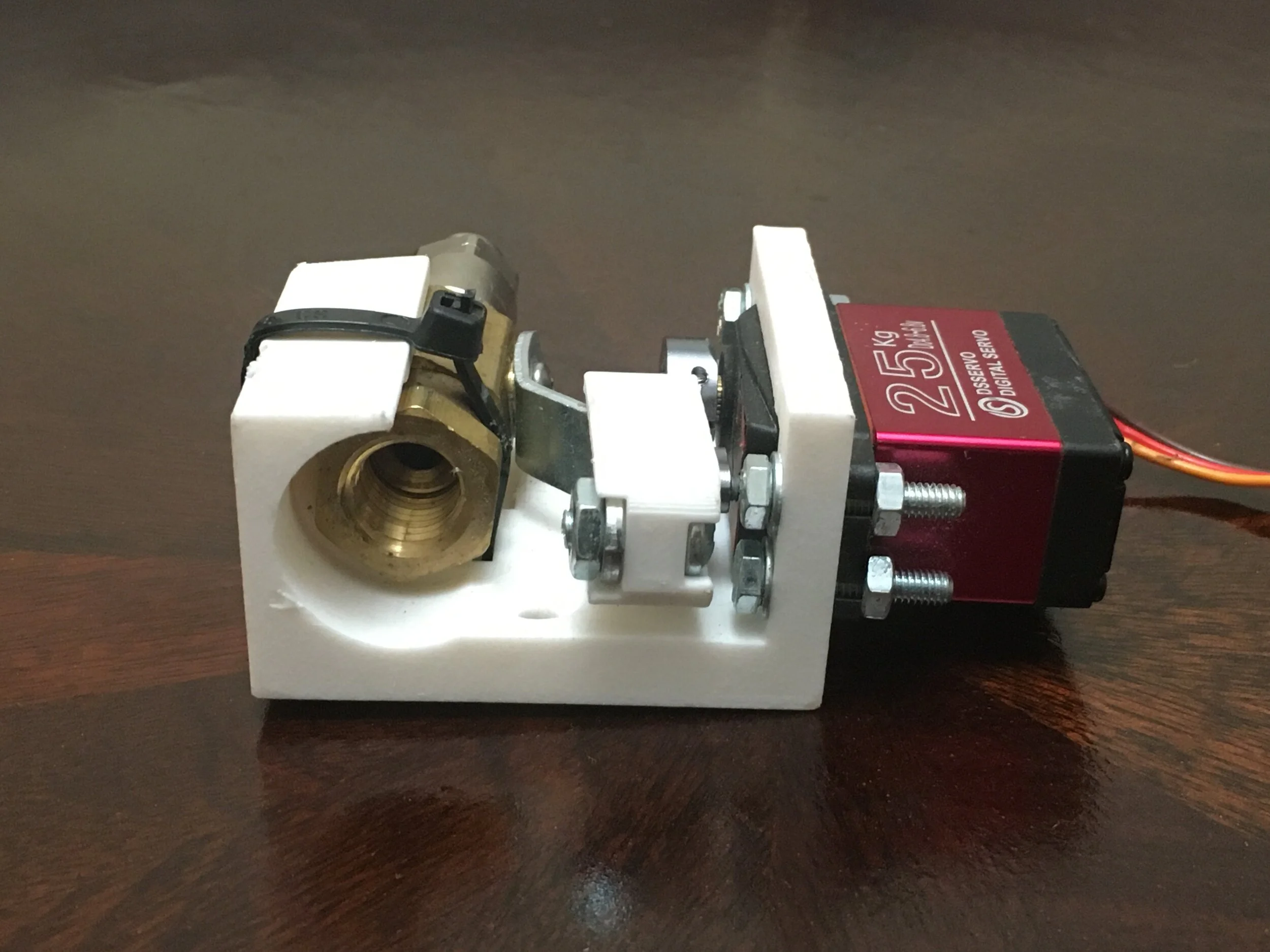
3. Install the DS3225 Servo into the Servo Valve Mount using the M4 screws, washers, lock washers, and nuts as shown.

4. Move the servo horn so it points out from the Servo Valve Mount (the Valve Closed position). Install the Servo Valve Handle Connector onto the Servo horn as shown, using the M3 Socket Head Cap Screw and washer. The M3 screw goes into the threaded hole closest to the end of the servo horn.
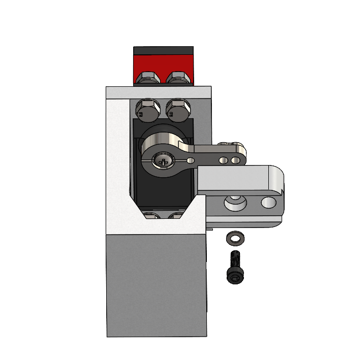
5. Move the servo horn back to the Valve Closed position, parallel to the back face of the Servo Valve Mount. Then, insert the ball valve into the mount, so that its handle slides into the Servo Valve Handle Connector.
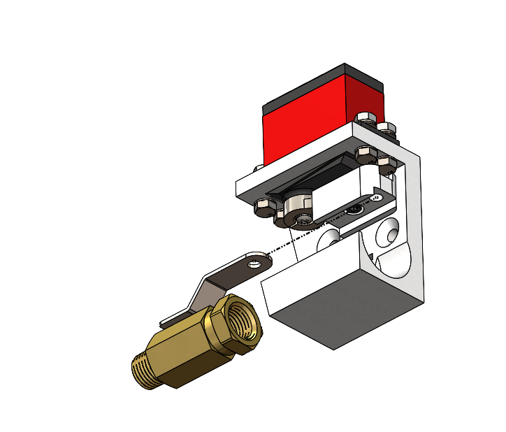
6. Move the servo horn and valve handle to the valve closed position, and install the #8-32 screw and nut through the Servo Valve Handle Connector and ball valve handle. The screw should fit through the existing hole in the valve handle. If it does not, drill as necessary.

7. Complete the assembly by securing the valve in place with a nylon zip tie as shown in the photo. The zip tie should pass through the small rectangular slot in the Servo Valve Mount.